
This is a popular exercise that I’d love to discuss with my students. The design is very practical and it reveals the basic idea how to generalise the ripple adder concept to create an iterative circuit for a synchronous counter. The requirement of having up or down control also challenges the understanding of the 2’s complement arithmetic which is usually introduced earlier.
The question
We want to build a up/down synchronous counter with an enable signal. The basic structure of the design is given as follows:
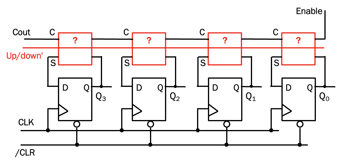
The design is iterative so that more bit slices which each contains a mystery block and a D-type flip-flop can be added to the end (left hand side of the diagram above) to extend the counter for more bits. But in this exercise, we focus on a 4-bit design. \(Q\) is the output of the counter and it counts up (e.g. 0100, 0101, 0110, ..) and down (e.g. 0011, 0010, 0001, …) depending on the control input \(up/down'\). There is also an \(Enable\) signal which starts or stops the counting in either up or down mode.
So the question is now:
- What should be the mystery (combinational) block?
- How to connect the \(up/down'\) and \(enable\) to the mystery blocks to fulfill the requirement? You may add some logic gates but they should be kept as few as possible.
Let’s work on the exercise and read on when you have your solution!
Hints / the partial solution
It is not too difficult to guess that the mystery block is a full adder. So now there are three bits of input to consider (i.e. \(A\), \(B\), \(C_{in}\)).
It is useful to write down the requirement in a table, with regards to the control inputs of the counter.
+----------+--------+-----------+
| up/down' | enable |     Q     |
+==========+========+===========+
|    0     |   0    | no change |
+----------+--------+-----------+
|    0     |   1    | count down|
+----------+--------+-----------+
|    1     |   0    | no change |
+----------+--------+-----------+
|    1     |   1    | count up  |
+----------+--------+-----------+
Clearly \(Q\) outputs of the flip-flops go back to input \(B\). And except for the first FA, \(C_{in}\) and \(C_{out}\) are chained together similar to a ripple adder. Therefore I would prefer to have the same input to all As of the FAs, while a specific input to the first \(C_{in}\) (let’s called it \(C_{in0}\) for now).
Let’s rewrite the above table based on this:
+----------+--------+----------+
| up/down' | enable |    Q     |
+==========+========+==========+
|    0     |   0    |no change |
+----------+--------+----------+
|    0     |   1    | 1111 + 0 |
+----------+--------+----------+
|    1     |   0    |no change |
+----------+--------+----------+
|    1     |   1    | 0000 + 1 |
+----------+--------+----------+
This means that when the counter counts up, \(A\) = 0 to all FAs and \(C_{in0}\) = 1. Similarly \(A\) = 1 and \(C_{in0}\) = 0 when we count down (1111 is the 2’s complement representation of -1, isn’t it?)
You can now try to complete the table for rows 1 & 3. Then you should be able to work out the additional gates and connections required (if not, you can read on to the full solution)
The last piece of puzzle / the full solution
If we follow from the partial solution, the complete table would be:
+----------+--------+----------+
| up/down' | enable | A + Cin0 |
+==========+========+==========+
|    0     |   0    | 1111 + 1 |
+----------+--------+----------+
|    0     |   1    | 1111 + 0 |
+----------+--------+----------+
|    1     |   0    | 0000 + 0 |
+----------+--------+----------+
|    1     |   1    | 0000 + 1 |
+----------+--------+----------+
where I added a trick on the first row to add 10000 = 1111 + 1 instead of 00000. The main reason is that I would like to match the bits with the complement of the \(up/down'\) signal. And from the truth table we can see that we need an XNOR gate to generate \(C_{in0}\). As a conclusion:
\[\begin{matrix} A & = (up/down')'\\ C_{in0} & = (up/down') \bar{\oplus} enable\\ \end{matrix}\]Two additional logic gates are added to complete the solution.
I will be sharing the VHDL implementation in a future post.